Question 4
(a)
State two uses of capacitors in electrical circuits, other than for
the smoothing of direct current. [2]
(b)
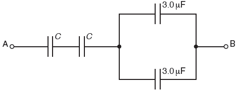
The combined capacitance between terminals A and B of the
arrangement shown in Fig. 7.1 is 4.0 μF.
Fig. 7.1
Two capacitors each
have capacitance C and the remaining
capacitors each have
capacitance 3.0 μF.
The potential
difference (p.d.) between terminals A and B is 12 V.
(i)
Determine the capacitance C. [2]
(ii)
Calculate the magnitude of the total positive charge transferred to
the arrangement. [2]
(iii)
Use your answer in (ii) to state the magnitude
of the charge on one plate of
1.
a capacitor of capacitance C,
2.
a capacitor of capacitance 3.0 μF.
[2]
[Total: 8]
Reference: Past Exam Paper – June 2016 Paper 42 Q7
Solution:
(a)
e.g.
storing
energy
blocking
d.c.
in
oscillator circuits
in tuning
circuits
in timing
circuits
(b)
(i)
{For the
capacitors in parallel, combined capacitance = 3 + 3 = 6.0 μF
The 2
capacitors C are connected in series to the parallel combination.
Combined
capacitance between A and B = 4.0 μF
1 / 4 =
1/6 + 1/C + 1/C }
1/6 + 1/C + 1/C = 1/4
C = 24 μF
(ii)
{The total
charge is determined using the total capacitance and the applied potential
difference.
Combined
capacitance between A and B = 4.0 μF
p.d.
between A and B = 12 V}
Q = CV
Q = 4.0×10-6 × 12
Q = 48 μC
(iii)
1.
{Current
is the flow of charge. So, we need to identify the flow of current on the
capacitors.
Current
flows into the two capacitors C. So, the total charge appears on C.
The total charge
is received by the capacitors in series.}
48 μC
2.
{At the
junction of the parallel combination, the current splits equally. So, the
charge is shared by the capacitors in parallel.}
24 μC


No comments:
Post a Comment
If it's a past exam question, do not include links to the paper. Only the reference.
Comments will only be published after moderation