
Question 9
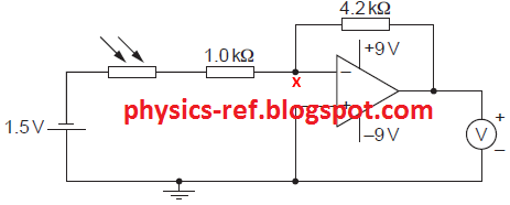
The circuit diagram of Fig. 9.1 is an amplifier circuit
incorporating an operational amplifier (op-amp).

Fig. 9.1
(a) (i) On Fig. 9.1, mark, with the letter X,
the virtual earth. [1]
(ii) Explain what is meant by a virtual
earth. [3]
(b) In bright sunlight, the light-dependent resistor (LDR)
has resistance 200 Ω.
(i) Calculate, for the LDR in bright sunlight, the voltmeter
reading. [3]
(ii) The sunlight incident on the LDR
becomes less bright.
State and explain the effect on the voltmeter reading of
this decrease in brightness. [3]
Reference: Past Exam Paper – June 2010 Paper 41 Q9
Solution:
(a) (i)
point X
shown correctly
(ii)
The open-loop gain of the op-amp is very large
(or infinite gain).
The non-inverting input (V+) is at 0
V (since it is connected to earth).
For the amplifier not to saturate, the
inverting input (V-) must be almost equal to the potential of the non-inverting
input (which is at 0 V).
So, the potential of the inverting input at
said to be at virtual earth.
(b)
(i)
{Total input
resistance = 1.0 + 0.2 = 1.2 kΩ}
total input
resistance = 1.2 kΩ
{For an
inverting amplifier, gain = - RF / RIN }
(amplifier) gain (= –4.2 / 1.2) = –3.5
{Gain = VOUT / VIN
VOUT
= Gain × VIN = -3.5 ×
-1.5}
(voltmeter)
reading = –3.5 × –1.5 = 5.25 V
(ii)
(The light
is less bright so,) the resistance of the LDR increases
{This decreases
the total input resistance.
Since gain =
- RF / RIN, the gain of the amplifier decreases.}
(the amplifier)
gain decreases
(so, the voltmeter) reading decreases
No comments:
Post a Comment
If it's a past exam question, do not include links to the paper. Only the reference.
Comments will only be published after moderation