FOLLOW US ON TWITTER
SHARE THIS PAGE ON FACEBOOK, TWITTER, WHATSAPP ... USING THE BUTTONS ON THE LEFT


YOUR PARTICIPATION FOR THE GROWTH OF PHYSICS REFERENCE BLOG

Wednesday, June 12, 2019

The circuit diagram of Fig. 9.1 is an amplifier circuit incorporating an operational amplifier (op-amp).


Question 9
The circuit diagram of Fig. 9.1 is an amplifier circuit incorporating an operational amplifier (op-amp).


Fig. 9.1

(a) (i) On Fig. 9.1, mark, with the letter X, the virtual earth. [1]

(ii) Explain what is meant by a virtual earth. [3]


(b) In bright sunlight, the light-dependent resistor (LDR) has resistance 200 Ω.
(i) Calculate, for the LDR in bright sunlight, the voltmeter reading. [3]

(ii) The sunlight incident on the LDR becomes less bright.
State and explain the effect on the voltmeter reading of this decrease in brightness. [3]


Reference: Past Exam Paper – June 2010 Paper 41 Q9


Solution:
(a) (i)
point X shown correctly
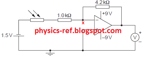


(ii)
The open-loop gain of the op-amp is very large (or infinite gain).
The non-inverting input (V+) is at 0 V (since it is connected to earth).
For the amplifier not to saturate, the inverting input (V-) must be almost equal to the potential of the non-inverting input (which is at 0 V).
So, the potential of the inverting input at said to be at virtual earth.


(b)
(i)
{Total input resistance = 1.0 + 0.2 = 1.2 kΩ}
total input resistance = 1.2 kΩ 

{For an inverting amplifier, gain = - RF / RIN }
(amplifier) gain (= –4.2 / 1.2) = –3.5 

{Gain = VOUT / VIN
VOUT = Gain × VIN = -3.5 × -1.5}
(voltmeter) reading = –3.5 × –1.5 = 5.25 V

(ii)
(The light is less bright so,) the resistance of the LDR increases

{This decreases the total input resistance.
Since gain = - RF / RIN, the gain of the amplifier decreases.}
(the amplifier) gain decreases
(so, the voltmeter) reading decreases

Tuesday, June 11, 2019

A ball is set in motion at P on a frictionless surface. It moves up slope PQ, along the horizontal surface QR and finally descends slope RS.


Question 24
A ball is set in motion at P on a frictionless surface. It moves up slope PQ, along the horizontal surface QR and finally descends slope RS.


Which graph could represent the variation with time t of the ball’s speed v as the ball moves from P to S?


Reference: Past Exam Paper – June 2017 Paper 12 Q6


Solution:
Answer: A.


The ball moves on a frictionless surface. That is, no frictional force acts on the ball and thus, no energy is wasted against friction.


From P to Q, the ball can be considered to have 2 components: a horizontal component and a vertical component.

The horizontal component remains unaffected (as there is no friction) while the vertical component is affected by the acceleration due to gravity which is downwards.


From P to Q, the vertical component of speed is upwards while the acceleration due to gravity g is downwards. This causes the speed of the ball to decrease. Since g is constant, the decrease in speed is also uniform [gradient is constant – a straight line in the graph]. [D is incorrect]


From Q to R, the ball moves horizontally. It does not have a vertical component. Since the horizontal component is constant, the speed is also constant from Q to R. [B is incorrect]


From R to S, the vertical component is downward and g is also downward. So, the speed increases uniformly.

In terms of energy,
From P to Q, KE - - > GPE    (KE and speed decrease)
From Q to R, GPE remains constant (constant height – KE and v does not change)
From R to S, GPE - - > KE    (KE and speed increase)
 

Since S is at the same level as P. the GPE is the same. And thus, the KE is also the same as before (and so, speed is also the same as before). So, because the ball ends up at the original level, it cannot be travelling faster at the end than it was travelling at the start. [C is incorrect].

Sunday, June 9, 2019

A circuit is set up as shown. The variable resistor is adjusted so that the ammeter reading decreases.


Question 28
A circuit is set up as shown.


The variable resistor is adjusted so that the ammeter reading decreases.

How do the readings of the voltmeters change?

reading on voltmeter P           reading on voltmeter Q
A                      decreases                               decreases
B                      decreases                               increases
C                     increases                                 decreases
D                     increases                                 increases


Reference: Past Exam Paper – June 2017 Paper 12 Q37


Solution:
Answer: B.

Ohm’s law: V = IR
Current I = V / R

The ammeter gives the value of current flowing in the whole circuit since the components are connected in series.

For the current in the circuit (ammeter reading) to decrease, the total resistance in the circuit should increase.


The resistance of the fixed resistor on the left cannot be increased. It can be concluded that it is the resistance of the resistor that has increased.


Voltmeter Q gives the potential difference across the variable resistor.
V = IR

Since the resistance of the variable resistor has increased, the p.d. across it (reading on voltmeter Q) also increases. [A and C incorrect]


The sum of p.d. in the circuit should be equal to the e.m.f. in the circuit. That is, the sum of readings on voltmeter P and Q should be equal to the e.m.f.
 

Since the reading on voltmeter Q has increased, the reading on voltmeter P should decrease. [B is correct]
Currently Viewing: Physics Reference |